Overview

Blind spot detection (BSD) is one of the core functions of the Auto Lane Change System (ALCS). The Field of View (FoV), angular detection of the curvature represented by sensors, leaves a fine trail of uncovered areas and as a result, certain blind spots remain. This presents a challenge to the driver switching lanes during traffic scenarios. If constant street congestion is considered, as well as blind spots of large public buses and heavy machinery like forklifts that maneuver slowly, the traffic incident statistics come as no surprise.

For in-motion vehicles to avoid collision, they must not lose image recognition at the rear and sides (left and right). Hence, it is essential that a high-level of detection accuracy without significant frame loss is captured by camera sensors. To achieve this, the sliding window technique, heat map, and thresholding functions can be employed on the light-weight, deep-learning-equipped embedded platform board (limited hardware).

This treatment of sensorial functions such as blind-spot detection needs applications such as APA (Automatic Park Assist), SVM (Surround View Monitoring), and more. In vehicles equipped with blind spot monitoring systems which work on standalone sensors or fusion, the following features can help original equipment manufacturers (OEMs) and Tier-1s to optimize the system:

  • Improved detection and monitoring accuracy compared to existing systems
  • Performance enhancement in terms of better relative velocity, distance, wide-angle max-range, curvature, and so on
  • In-motion as well as stationary object detection without any frame loss under various operating conditions as set forth in requirements

Introduction

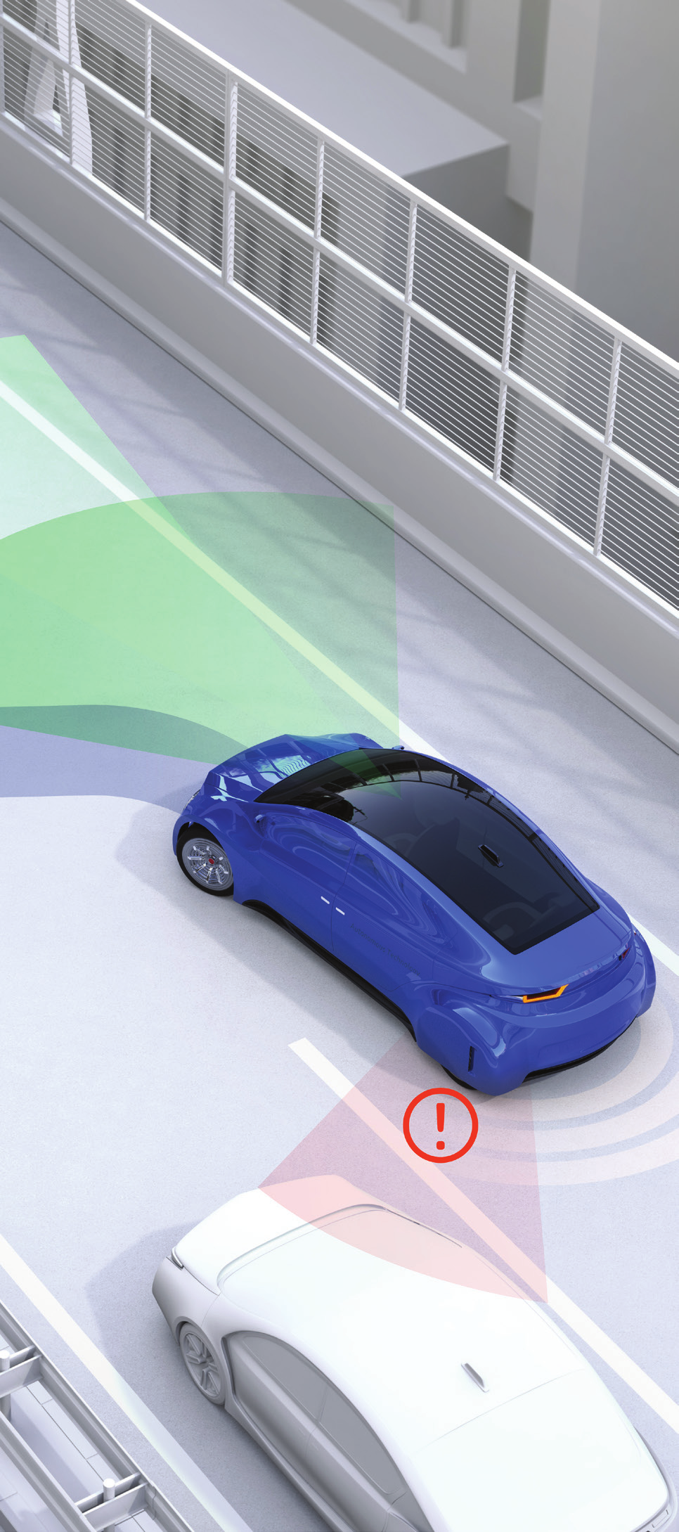
In a blind spot monitoring system, electronic detection device(s) are mounted on the sides of the vehicle, often in the vicinity of the external rear view mirrors or near the rear bumpers. These devices send out either electromagnetic waves (usually in radar wavelengths) or take computer-processed images with a digital camera. Images are then analyzed using optical flow techniques and frame difference to detect pixels that move in the same direction as the ego (host) vehicle.

Recent reports talk of the development of a sensor-fusion based system for blind spot detection by an electronics manufacturer targeted toward the small and medium range of passenger and commercial vehicles.

Challenges pertained to accuracy and real-time operation of camera and radar algorithms. This problem can be rectified with reliable output by designing and developing factors such as CFAR (Constant False Alarm Rate) detection, clustering, tracking, optimizing, and porting onto r-Car V3M SDK-interfaced with an image recognition engine (IMP-X5-V3M) and an image signal processor (ISP), rendering the camera image distortion correction application (IMR).

This paper focuses on the implementation of a cost-effective blind spot detection solution which can be simulated with adverse scenarios. Monocular camera parameters such as focal length and intrinsic and extrinsic parameters are used for estimating the vehicle location in the Region of Interest (RoI). Once the object is detected using frame difference to eliminate false alarms, we can calculate the direction of motion of vehicles using optical flow and filtering vehicles which move in the reverse direction.

 Blind spot monitoring system

Development Setup to Implement BSD Solution

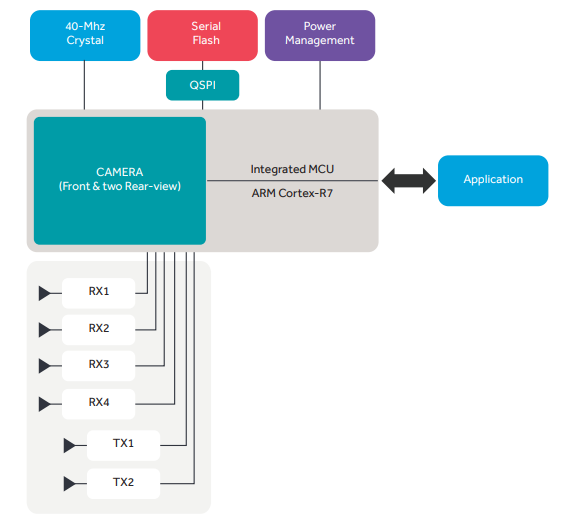
The setup consists of a custom board built using a Renesas’ r-Car V3H SoC device. This has a self-contained video encoding signal processor (VSPD) for inter-device video transfer (iVCP1E) single-chip sensor that simplifies the implementation of automotive vision sensors in the 10~60Hz band. The figure below explains the basic architecture, which consists of an antenna, ARM R7, CAN, and other interfaces.

tools-for-stack-customization

Tools for stack customization/optimization:
MS Visual studio 2012, OpenCV library, Eclipse IDE, r-Car V3H


Challenges


Factors determining the accuracy of object detection

  • Relative distance: Object detection was expected to work with high accuracy across a range of relative distances. While object detection algorithms worked fine for shorter distances, the accuracy was compromised for longer distance.
  • Angle of object: Targeted accuracy of 0.1 degrees
  • Reflections: Since the systems were used in large vehicles, their own reflections resulted in false detections.
  • Roadside reflections: Roadside radar clutter reflections of pipes, fences, and so on should not be detected, while vehicles should not be missed.
  • Desired detection accuracy: Targeted misdetections at 0% and false detections at 1%.

Real-time performance of object detection: The algorithms do not run in real time at 30fps resulting in frame losses, and hence result in delayed and inaccurate detection.

Proposed Solution

To demonstrate our system, a proof of concept prototype is being developed which relies entirely on customized off-the-shelf image processing algorithms, with minimum dependency on OpenCV (open source computer vision library by Intel) across target platforms. Algorithms across the sensor fusion processing and object detection pipeline such as range FFT, Doppler FFT, CFAR for thresholding, ESPRIT for angle detection, DBSCAN for clustering, and Kalman filtering for tracking are the factors considered for implementation, integration, and optimization for real-time performance. The algorithms can be fine-tuned for the customer use-case to deliver desired outcomes.

block-diagram-of-base-software

Proposed Flow Chart


Employing OpenCV, frames are fetched from video to convert into matrix.

01 Image Enhancement

The first step is selecting the Region of Interest so that only the core part of the image is processed. The raw image is blurred using median blurto remove salt and pepper noise.

02 Motion Estimation

Absolute Frame Difference is used for motion estimation. It calculates the per-element absolute difference between two arrays or between an array and a scalar.

03 Direction Estimation

Optical flow is used to compute the motion of the pixels of an image sequence. It provides a dense (point to point) pixel correspondence. The challenge in correspondence is to determine where the pixels of an image at time t are in the image at time t+1. The number of features extracted can be varied by altering parameters.

04 Object Direction

Thresholding is carried out for object detection which converts a grayscale image to a binary one. Beyond the threshold, the number of white pixels in the frame is matched, and after tracking the result for a group of frames, object marking is done.

05 Object Classification

Once the object is detected in the RoI region, Haar Cascade is used for vehicle classification. It works on the principle of extracting features from a set of positive and negative databases of the object to be detected.


proposed-flow-chart

The figure below shows the outline of a host car with sensor cones; the blind spot is indicated by green color

host-car-with-sensor-cones

Here, the sensor placements must be such that the sensor RoI covers the maximum area of the blind spot. The logic is designed such that the same sensor can work at high speeds as auto lane change assist, and in heavy traffic at low speeds, the range has been reduced to detect collision.

The figure below shows a vehicle approaching the blind spot of a host vehicle.

blind-spot-of-a-host-vehicle-1

Common Haar features


01 Edge features

02 Line features

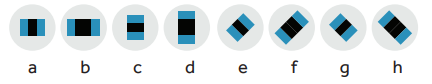
03 Center-surround features

04 Warning display

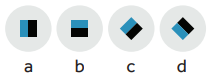
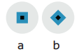
Blind spot detection (BSD) warning is displayed by the image icons below.


When BSD Region of Interest is free (No Vehicle condition)

When BSD Region of Interest is occupied (Vehicle detected)


Following scenarios are the possible methods for BSD activation:

Within the blind spot area of host vehicle (ego), the onset vehicle behind the ego car moves in the direction of sensor zone (left and right) and enters the zone from the free area to trigger BSD via the methods depicted through image pre-processing, motion/direction detection, followed by object detection and classification.

bsd

Expected output samples


bds-no-active-1
bds-active-1


Above images “531” and “661” illustrate the optimization result based on RoI occupied through FoV and angular detection of the traffic vehicle (car) within the estimated distance from the ego vehicle

Summary

This solution is expected to detect stationary as well as moving objects without any frame loss under various operating conditions as set forth in requirements including relative velocity, max range, distance etc. It uses the Kalman filtering technique for iterated estimation in motion tracking and Yolov4 for detection rate improvisation factors.

The angle of the object is calculated with an accuracy of 0.1 deg, delivering an improvement over off-the-shelf algorithms which are typically capable of an accuracy of 1.5~2 deg.

Real-time performance across various configurations is certain to be achieved.

summary

Solution Benefits

  • Toolchain integration, development excellence (e.g., defect resolution time), and ready-to-use software stacks will become key differentiators, reducing customer development efforts and accelerating time-to-market
  • Value-creation for reusable libraries
  • End-to-end product engineering (off-the-shelf)
  • Scope for single-sourcing solutions and strategic partnerships
  • Sustainable solution model as one-time royalty license and or non-recurring engineering (NRE) efforts

All this ensures that the software life cycle will extend beyond six to eight years after SoP (start-of-production)

549

Conclusion

The proposed solution presents a real-time embedded blind spot safety assistance system to detect the vehicle or objects appearing in the blind spot area.

This algorithm solves most problems occurring in various kinds of environments, especially urban traffic scenarios. It also overcomes the weather conditions and maintains the high performance no matter what time it is. From the experimental results, it is obvious that the proposed approach not only works well on highways but also has good performance in the urban, delivering better performance both in detections and false alarms.

As an engineering services provider, Cyient works closely with the industry experts, equipment manufacturers, and aftermarket customers to align with automotive industry trends through our focus areas of megatrends "Intelligent Transport and Connected Products," "Augmentation and Human Well-Being," and "Hyper-Automation and Smart Operations."


About Cyient

Cyient (Estd: 1991, NSE: CYIENT) is a leading global engineering and technology solutions company. We are a Design, Build, and Maintain partner for leading organizations worldwide. We leverage digital technologies, advanced analytics capabilities, and our domain knowledge and technical expertise, to solve complex business problems.

We partner with customers to operate as part of their extended team in ways that best suit their organization’s culture and requirements. Our industry focus includes aerospace and defense, healthcare, telecommunications, rail transportation, semiconductor, geospatial, industrial, and energy. We are committed to designing tomorrow together with our stakeholders and being a culturally inclusive, socially responsible, and environmentally sustainable organization.

For more information, please visit www.cyient.com