Intelligent Engineering
Our Intelligent Engineering solutions across products, plant and networks, combine our engineering expertise with advanced technologies to enable digital engineering & operations, develop autonomous products & platforms, and build sustainable energy and infrastructure
.png?width=774&height=812&name=Master%20final%201%20(1).png)
Introduction
The air vehicle, from takeoff to touch down, undergoes significant mechanical and pressure loads. Numerous unpredictable factors impact the airline’s structural integrity. Aero engines counteract these loads, ensuring safety and structural integrity. The paper covers key engine development phases, and aspects such as:
- Significance of loads across engine development phases and their design impact
- Modeling, integration, and validations:
- Methods to ensure load accuracy in engine design through modeling, integration, and validation
- Engine backbone bending and cowl load sharing
- Analyzing backbone bending concepts and load distribution, with a focus on cowl load sharing
- Understanding engine behavior under dynamic environments
- Analyzing case studies for insights into engine behavior in dynamic conditions, offering real-world understanding
The paper aims to provide a comprehensive understanding of loads in gas turbine engines, from development phases to practical applications in design and dynamic behavior. Readers will gain insights into leveraging load information to enhance engine performance and reliability.

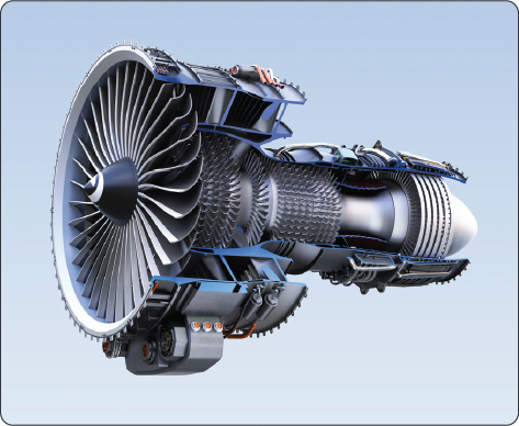
Engine Structure Overview
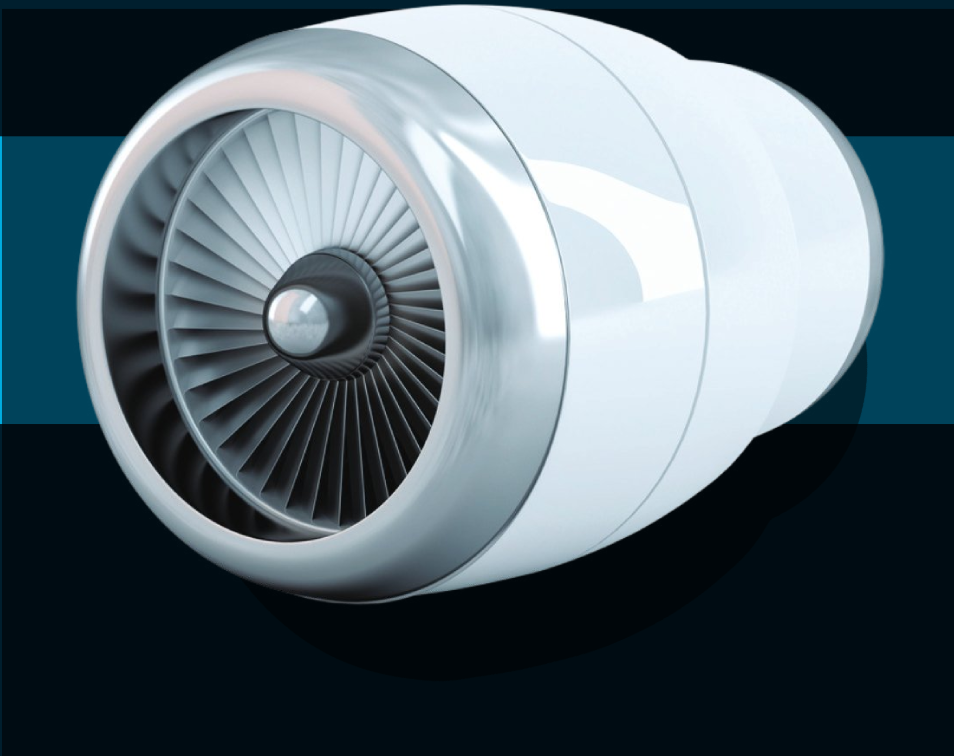
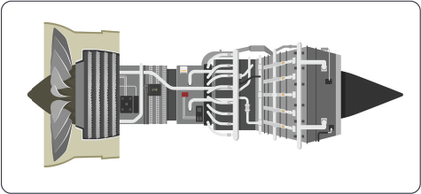
Engines are comprised of three components: core, nacelle, and airframe hardware. The core includes cases, frames, rotors and mounts. Nacelles optimize aerodynamics with inlet, fan cowl, thrust reverser, nozzle, and tail cone.
Components pertinent to airframes include Pylons/Struts and Wings/. CAE engineers use FE modeling for virtual components, conducting static and dynamic analyses, ensuring structural integrity.
Key Engine Development Phases
The diagram below depicts the aircraft structure development process applicable to gas-turbine engines (GTE). Loop1 establishes an Integrated Finite Element Model (IFEM), which will get refined post-review and will be used in the rig testg. Loop1.5 is created for the Fan Blade Off (FBO) test. IFEM calibration leads to Loop 2, representing real hardware. Loop 2 results aid FAA certification and hardware design. Loop1 loads inform Conceptual Design Review (CDR), while Loop 2 loads facilitate final FAR certification, ensuring systematic design evolution and validation.
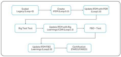
The diagram illustrates a schematic process in the development of aircraft structures, a methodology that is also applicable in the gas-turbine engine industry. With a few exceptions, the procedures employed in the design and development of gas turbine engines closely mirror those of aero-structural activities.
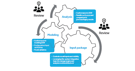
Inputs collection
The process begins with compiling data for modeling engine components, including 3D Unigraphics (UG) models, material properties, weight, center of gravity details, and key interfaces. The Design System Integration team gathers this data. engine components will be constructed based on these inputs by following Engineering Standard Work (ESW) guidelines. Then, integrate engine with the aircraft. The core engine consists of cases, frames, bearing supports, and rotors, primarily modeled using 2D shell elements. Loads are applied to a detailed Finite Element Model (FEM) for stress analysis. Nonstructural mass (NSM) elements reconcile weight discrepancies, and interface locations are meticulously maintained as per the Interface Control Document (ICD). Integration emphasizes accurate interface locations across all models.
Nacelle, mounts, pylon, and wing
This section explains the nacelle and airframer components, including the thrust reverser and pylon-wing support system, crucial for jet engine function.
IFEM Integration and Validation
All discussed models, including those of the core engine, external suppliers, nacelle manufacturers, and airframer, are integrated for validation. Three types of checks are conducted: weight validation ensures correct weight and center of gravity; rigid body check confirms free movement; and normal modes analysis identifies any unintended constraints or mechanisms.
.png?width=228&height=173&name=Figure%206.%20IFEM%20sub-assemblies%20and%20mounting%20locations%20of%20aero%20engines%20(1).png)
.png?width=227&height=173&name=Figure%206.%20IFEM%20sub-assemblies%20and%20mounting%20locations%20of%20aero%20engines%20(2).png)
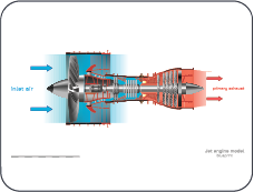
Types of Aero Engine Loads
Aero engines endure four main load types: thrust, inertial, vibration, and thermal loads. Thrust loads pertain to engine force variations. Inertial loads assess acceleration effects. Vibration loads result from engine dynamics. Thermal loads evaluate the structural impact of temperature fluctuations.
.png?width=229&height=173&name=Types%20of%20Aero%20Engine%20Loads%20(2).png)
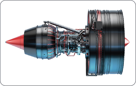
Engine Backbone Bending
Engine deflects due to applied loads, known as engine backbone bending, are caused by asymmetry relative to mounts. Loads such as take-off rotation, aerodynamic, inertial, and engine thrust induce this bending, highest during takeoff. Cases and rotors bend differently, affecting aerodynamic efficiency and compressor stability. Design considerations aim to minimize blade tip-to-case closures, ensuring optimal operating efficiency and compressor surge margin.
Cowl Load Sharing (CLS)
CLS acknowledges the structural capacity of the cowl and thrust reverser. If backbone bending exceeds limits, distributing some load to the cowl is a solution, specified as a percentage. Since cowl design is typically separate from the engine, a cowl load sharing percentage is agreed upon, enabling parallel design processes. Nacelle also carries load to minimize engine bending, making cowl load sharing a compromise.
Fan Blade Off
Fan Blade Off (FBO) refers to a fan blade detaching from its root, typically due to material failure, fatigue, or foreign object damage. The FAA mandates engine tests to demonstrate containment without fire or failure for at least 15 seconds. FBO-induced structural loads and vibration may damage nacelles, equipment, mounts, and airframe. Traditionally, these vibratory loads are considered insignificant compared to other design loads.

Wind-Milling and Its Impact
Wind-milling occurs after a fan blade detaches mid-flight, causing the engine to rotate due to incoming airflow, known as “wind-milling imbalance.” This rotation with an asymmetric fan generates large out-of-balance forces, potentially leading to rubs and impacts. Dynamic analyses represent component modes without considering strength and structural endurance.
Engine Design Phase
The design phase of an aero engine is critical, setting the course for the next seven-eight years of development. Disruptions can lead to significant losses. Challenges discussed earlier should guide load management during design. Designs undergo rigorous evaluation for structural analysis, manufacturability, and costing.
Load Analysis, Simulation, and Mitigation
Growing computational power enables optimal solutions for industrial problems. Numerical simulations constructed from FE models predict, and analyze loads in aero-engines, aiding CAD model optimization. Experimental testing validates analytical predictions, reducing costs and saving billions for the aviation industry.
Load Mitigation Strategies
Advanced materials affect engine load bearing. Research uses exotic materials in aeroengines to reduce weight without compromising performance. Active load control systems adapt technologies for load mitigation.

5G technology in agriculture
The advent of 5G technology will revolutionize global farming landscapes and will open up multiple ways to establish and grow precision farming. The figure below shows that every element in modern agriculture once connected to a high speed and high throughput 5G cellular network, works in tandem with the other to optimize resources and maximize yield. The imagery generated from SAR and GPR demand throughput for transferring them to a distant and central location/data cloud. Similarly, to control farming equipment remotely, a low latency communications network in inevitable.
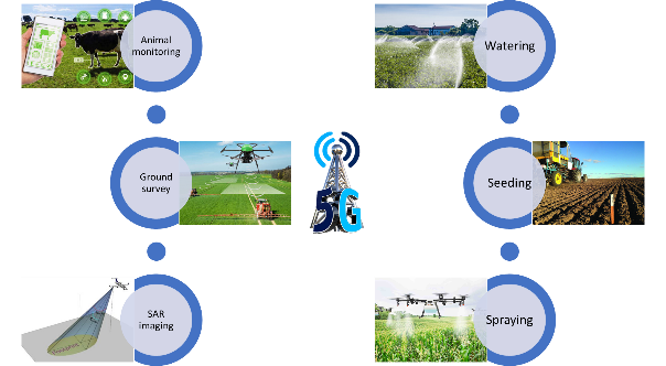
Figure 10. Uses of 5G technology in agriculture
About the Author

Vishnu Gaddam, an aerospace professional with Cyient since 2011, brings over 15 years of experience in the field. His journey began at GE Aviation, where he assessed both small and large aero engines for static and dynamic behavior. At Cyient, Vishnu works on complete aero engines and evaluates loads under normal and extreme operational conditions. He is a certified Project Management Professional (PMP), Certified Scrum Master (CSM), and Six Sigma Green Belt. As a subject matter expert, Vishnu collaborates across teams, fostering knowledge exchange.