.png?width=774&height=812&name=Master%20final%201%20(1).png)


Introduction
Electrification is reshaping mobility, energy infrastructure, and industrial operations. Lithium-ion batteries sit at the center of this transformation. However, battery performance and safety depend on intelligent control.
The global Battery Management System market reflects this shift. In 2024, the BMS market was valued at approximately USD 8.5 billion and is projected to exceed USD 31 billion by 2030, growing at a CAGR of nearly 25%.This growth is driven by EV adoption, expansion of renewable energy storage, and increasing regulatory focus on battery safety.
A BMS acts as the intelligence layer of the battery pack. It continuously monitors electrical and thermal behavior, predicts performance, prevents failure conditions, and enables efficient energy utilization across diverse operating environments.

High-Level Solution and Solution Details
-
A Battery Management System
Mitigates battery risks by integrating sensing, estimation, protection, balancing, and communication within a closed-loop control framework.
At a high level, a BMS:-
Monitors real-time electrical and thermal parameters
-
Estimates internal battery states using model-based algorithms
-
Enforces safe operating limits
-
Balances cells to maximize usable capacity
-
Communicates with external systems for coordinated control
In advanced implementations, the BMS combines physics-based modeling with adaptive algorithms to manage nonlinear battery behavior under dynamic loads. Modern systems increasingly integrate edge processing with cloud analytics to enable predictive diagnostics and performance optimization.
-
-
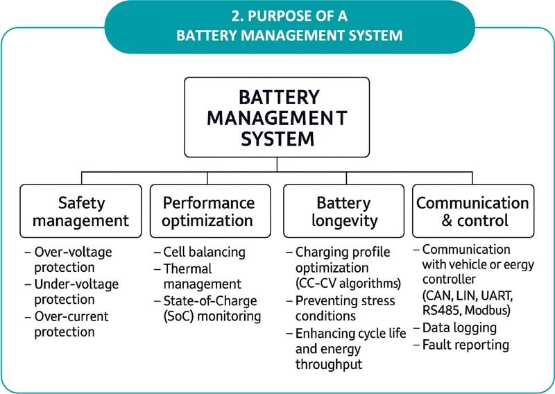
Purpose of a Battery Management System
A Battery Management System (BMS) acts as the "brain" of a rechargeable battery pack, ensuring it operates safely, efficiently, and for as long as possible. It is particularly critical for lithium-ion batteries, which are sensitive to being pushed outside their safe operating limits.
Core Purposes of a BMS-
Safety & Protection: The primary goal is to prevent hazardous conditions like fires or explosions. The BMS acts as a safety net by:
-
Preventing Overcharging: Shuts down the charger if a cell's voltage gets too high.
-
Avoiding Deep Discharge: Disconnects the load if voltage drops too low, preventing permanent chemical damage.
-
Overcurrent Protection: Limits power output during rapid spikes to protect the cells.
-
Short Circuit Detection: Monitors for faults and isolates the battery if one occurs.
-
-
Performance Optimization: A BMS maximizes the usable energy and power of the entire pack.
-
Cell Balancing: Equalizes the charge levels across all individual cells so the pack isn't limited by its weakest cell.
-
Thermal Management: Activates cooling or heating systems to keep the battery in a "Goldilocks" temperature range (typically 20–40°C).
-
-
State Estimation & Reporting: It calculates and communicates critical data to the user or other vehicle systems.
-
State of Charge (SOC): Acts as a "fuel gauge" to show how much energy is left.
-
State of Health (SOH): Tracks long-term degradation to estimate the battery's remaining useful life.
-
Range Estimation: In EVs, it uses SOC data to calculate how many more miles can be driven.
-

-
-
Longevity & Reliability: By keeping the battery within its Safe Operating Area (SOA), the BMS prevents premature aging, significantly extending the life of the cells.
-
In the context of communication and control, a Battery Management System (BMS) acts as a specialized industrial or automotive controller that bridges the gap between raw battery data and the larger system's operation (like an electric vehicle or solar inverter).
1. Communication Layers
A BMS uses a hierarchy of communication to move data from individual cells up to a user-facing dashboard:
-
Internal (Intra-BMS): Connects individual cell monitoring chips to the main BMS controller. It often uses high-speed, short-distance protocols like I2C or SPI to handle thousands of readings per second.
-
External (System-Level): Connects the BMS to external "masters" like a Vehicle Control Unit (VCU) or a Solar Inverter. This typically uses robust, noise-resistant protocols:
-
CAN Bus (Controller Area Network): The automotive standard for real-time communication between the BMS, motor, and charger.
-
Modbus (RTU/TCP): Widely used in industrial energy storage and solar systems to talk to inverters.
-
RS485 / UART: Common for stationary batteries and PC-based diagnostic tools.
-
Bluetooth/Wi-Fi: Used in "Smart BMS" units for mobile app monitoring and remote firmware updates.
2. Control Functions
The "Control" aspect refers to how the BMS uses processed data to actively manipulate the system:
-
Closed-Loop Charging: The BMS "commands" the charger to adjust voltage and current in real-time based on the battery's temperature and health. This is more efficient than "open-loop" charging, which uses fixed, preset values.
-
Load Shedding & Derating: If the BMS detects a cell is getting too hot or low on voltage, it sends a control signal to the motor controller to derate (limit) the power output, preventing a total system shutdown while protecting the battery.
-
Isolation Control: In emergencies, the BMS controls high-voltage contactors (heavy-duty relays) to physically disconnect the battery from the rest of the system to prevent fires or electrocution.
-
Thermal Control: Based on internal sensor data, the BMS activates cooling fans, pumps, or heaters to maintain the "Goldilocks" temperature range.
3. Key Data Exchanged
In a communication-enabled system, the BMS constantly reports the following to other controllers:
-
Charge/Discharge Limits: Tells the motor how much power it is allowed to take right now.
-
Fault Codes: Instant alerts for overvoltage, temperature spikes, or sensor failures.

-
3. BMS Architecture Overview
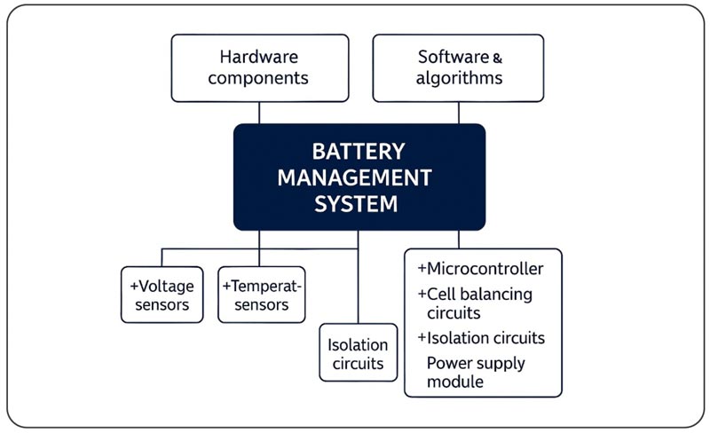
A typical BMS architecture consists of hardware and software layers that operate in coordination.
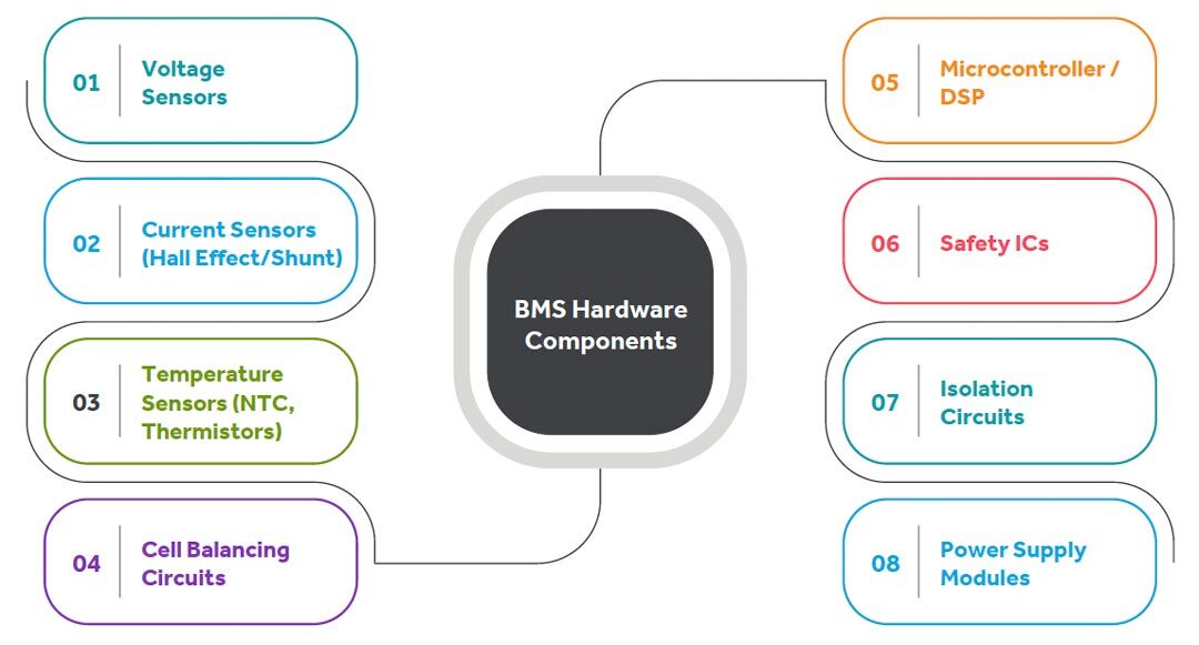
3.1 Hardware Components
|
Component |
Purpose |
Key Details |
| Voltage Sensors | Measure cell and pack voltage | BMIC / AFE, RC filtering, ADC channels; ±1–3 mV accuracy; supports over-voltage and under-voltage protection; critical for SOC estimation and cell balancing |
| Current Sensors | Measure charge and discharge current | Shunt: low-ohmic resistor, differential amplifier/current sense IC; high accuracy, low cost; power loss, no isolation. Hall-effect: magnetic field-based, galvanic isolation; low heat dissipation; slightly lower accuracy, higher cost |
| Temperature Sensors | Monitor cell and pack temperatures | NTC, PTC, digital sensor ICs; placed on cell surface, between cells, on busbars/connectors; supports overtemperature protection, derating, and thermal management |
| Cell Balancing Circuits | Equalize cell voltages | Passive: bleed resistors + MOSFETs, heat dissipation; simple, low cost, reliable. Active: inductive/capacitive transfer, DC-DC conversion; high efficiency, faster balancing; higher complexity and cost |
| Microcontroller / DSP | Central control and decision-making | Automotive-grade MCU / DSP with ADCs, timers, watchdogs, Flash, RAM, EEPROM; handles SOC / SOH estimation, diagnostics, balancing, and communication; often ASIL-B / ASIL-D capable |
| Safety ICs | Independent hardware-level fault protection | Over-voltage / under-voltage, over-current, short circuit detection, redundant shutdown paths; works even if MCU firmware fails; required for functional safety compliance |
| Isolation Circuits | Protect low-voltage electronics and users | Digital isolators, isolation amplifiers, opto-couplers; used for HV-LV communication and sensing isolation; typical isolation rating: 1 kV to 5 kV |
| Power Supply Modules | Provide stable power to BMS electronics | Powered by HV battery pack or auxiliary 12 V supply; includes isolated DC-DC converters, buck regulators, and LDOs; designed for wide input range, EMI/EMC robustness, and separate analog/digital supplies |
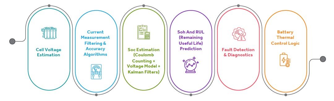
3.2 Software & Algorithms
BMS software is responsible for accurate state estimation, safety assurance, performance optimization, and lifetime management of the battery pack. It transforms raw sensor data into reliable decisions for protection, control, and optimization.
|
Component |
Description |
Key Functions |
| Cell Voltage Estimation | Ensures accurate and reliable measurement of individual cell voltages for protection, balancing, and state estimation. |
|
| Current Measurement Filtering and Accuracy Algorithms | Provides high accuracy pack current measurement, essential for energy tracking and safety. |
Sensors Used:
Key Functions:
|
| State of Charge (SoC) Estimation | Estimates available charge in the battery accurately under all operating conditions using hybrid approaches. |
Methods:
Key Functions:
|
|
State of Health (SoH) and Remaining Useful Life (RUL) Prediction |
Assesses battery aging and predicts remaining service life. |
|
|
Fault Detection and Diagnostics (FDD) |
Ensures functional safety through early fault detection and system protection. |
Fault Categories:
|
|
Battery Thermal Control Logic |
Maintains batteries within safe and optimal temperature limits to maximize performance and lifespan. |
|
4. Key Functional Blocks
4.1 Measurement & Sensing Layer
-
This layer monitors:
-
Individual cell voltages
-
Pack current
-
Ambient and cell temperatures
-
Isolation resistance (for EVs)
Measurement accuracy directly influences state estimation and safety decisions.
4.2 Cell Balancing
Two types of balancing improve pack consistency:
Passive Balancing
-
Uses resistors to burn excess energy.
-
Simple, low cost
-
Heat generation is a drawback.
Active Balancing
-
Transfers charge between cells
-
Higher efficiency
-
Ideal for EV and large energy storage systems
4.3 Control & Decision Engine
This engine implements:
-
Protection logic
-
Fault detection
-
Thermal control
-
Charge/discharge control
In automotive systems, this layer aligns with ISO 26262 functional safety requirements.
4.4 Communication Layer
Common protocols include:
-
CAN bus (EV industry standard)
-
SMBus (laptops)
-
Modbus/RS485 (industrial energy storage)
Reliable communication ensures coordination with vehicle control units, chargers, and supervisory systems.
5. Types of Battery Management Systems
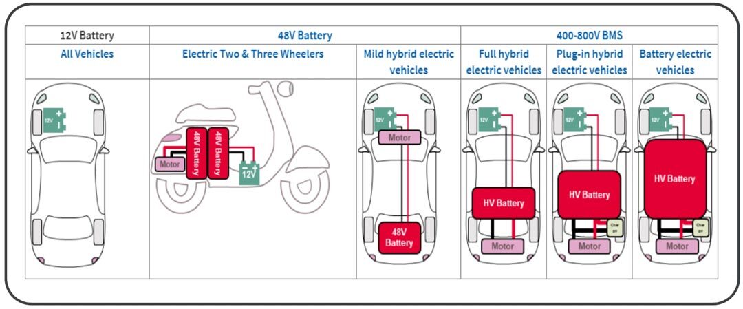
5.1. Based on Voltage BMS is broadly classified into two types (UNECE 2013).
|
Category |
Voltage Range |
Typical Applications |
Additional Classification |
|
Low Voltage (LV) |
≤ 30 V AC and ≤ 60 V DC |
Light electric vehicles, hybrid vehicles, two and three-wheelers |
Low Voltage Class 1 |
|
High Voltage (HV) |
30–1000 V AC or 60– 1500 V DC |
Electric automotive traction systems, stationary Energy Storage Systems (ESS) |
Class 2: ≤ 600 VAC / ≤ 900 V DC Class 3: ≤ 1000 V AC / ≤ 1500 VDC |
5.2. Based on application and complexity:
|
Architecture Type |
Structure |
Typical Use Cases |
Advantages |
|
Centralized BMS (Fig 1)
|
Single controller monitors, balances, and controls all cells. Entire monitoring circuitry housed in one assembly. Uses wire harness (N+1 wires for N cells). | Low-to-mid power battery packs |
|
|
Decentralized/ Modular BMS
|
Battery pack divided into identical modules. One module acts as master; others function as remote measurement units. |
Electric scooters and rickshaws (48V–60V lithium-ion packs, 1.2–2.5 kWh) |
|
|
Distributed BMS (Fig 3)
|
Electronics integrated directly on individual cell boards. Minimal tap wiring; communication wires connect cell boards to central controller. | Passenger and commercial EVs, grid-scale ESS |
|
.jpg?width=200&height=190&name=Centralized-BMS-(Fig-1).jpg)
.jpg?width=200&height=188&name=Decentralized-Modular-BMS-(Fig-2).jpg)
.jpg?width=200&height=176&name=Distributed-BMS-(Fig-3).jpg)

7. Future Trends in BMS (2025–2031 and beyond)
The future of BMS is wireless, intelligent, software-defined, modular, cyber-secure, and chemistry-agnostic — enabling safer, more efficient, and longer-lasting batteries.
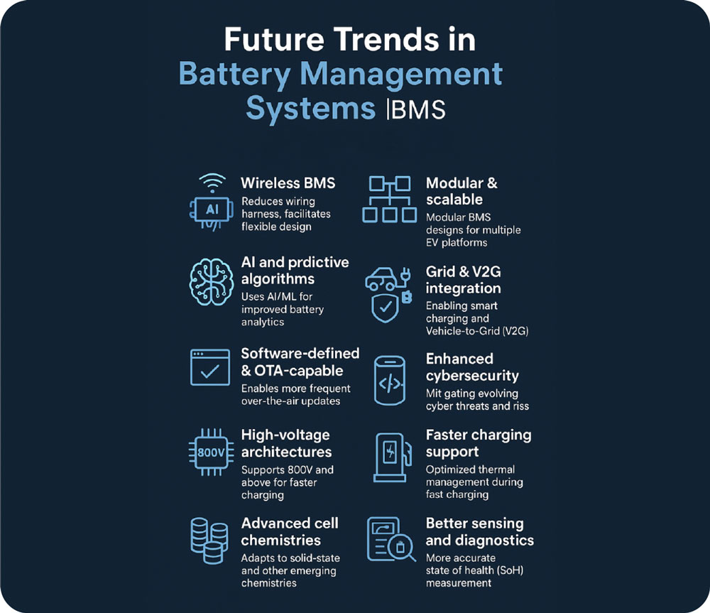
9. Future Roadmap
The next generation BMS will integrate:
Business Benefits/ Best Practices
Battery Management Systems as a Service (BMSaaS) provides cloud-based or subscription-driven management for battery packs, offering remote monitoring, data analytics, predictive maintenance, and optimization for performance, safety, and longevity, moving beyond just hardware to deliver intelligent battery oversight as a continuous service, crucial for EVs, storage, and IoT devices. It uses AI/ML to analyze real-time data (voltage, temp, SOC, SOH) and offers insights for better battery life, fleet management, and efficient energy use, turning battery data into actionable intelligence.
Key Components & Functions of BMSaaS:
-
Data Collection: Gathers real-time data from individual cells (voltage, current, temperature).
-
Health & Status Monitoring: Calculates State of Charge (SOC) and State of Health (SOH).
-
Safety & Protection: Prevents overcharging, over-discharging, and overheating.
-
Cell Balancing: Equalizes cell voltages for uniform performance.
-
Data Analytics & AI: Uses algorithms to predict failures, optimize usage, and extend lifespan.
-
Remote Management: Allows for over-the-air updates and remote diagnostics.
Benefits of the "As a Service" Model:
-
Cost-Effective: Reduces upfront hardware investment.
-
Scalability: Easily adapts to growing battery fleets.
-
Expertise: Provides advanced analytics and AI without requiring in-house specialists.
-
Improved Performance: Optimizes charging, discharging, and balancing.
-
Enhanced Safety: Proactive monitoring catches issues before they become critical.
Engineering BMS Platforms for Scalable Electrification
While modern BMS architectures continue to evolve toward wireless connectivity, predictive analytics, and cloud integration, implementing these systems at scale requires deep expertise across hardware design, embedded software, safety engineering, and system integration.
Cyient supports OEMs and energy-storage innovators in designing next-generation battery platforms that combine intelligent sensing, distributed architectures, and secure communication frameworks.
Building on our experience in embedded systems and electrification programs, Cyient has developed frameworks for Wireless Battery Management Systems (wBMS) that simplify pack architecture and enhance scalability. Unlike conventional wired BMS designs, wireless systems eliminate extensive harnessing between cells and controllers, reducing weight, improving modularity, and simplifying manufacturing.
 Cyient’s wireless BMS framework enables:
-
Reduced wiring complexity across large battery packs
-
Improved system reliability through distributed monitoring
-
Scalable battery architectures for EV and energy-storage platforms
-
Real-time battery diagnostics and predictive insights
-
Secure communication and OTA update readiness
By combining embedded engineering, digital analytics, and system validation capabilities, Cyient helps manufacturers transform battery packs into intelligent, connected energy systems—supporting safer operation, longer battery life, and more efficient electrification platforms.

About the Author
 |
Arun Kumar Jayasingh has over 23 years of engineering expertise, leading large-scale design, digital engineering, and operations-transformation programs across global aerospace and industrial domains. As Delivery Director at Cyient Ltd, he oversees Design and Electrical engineering Service area across multiple geographies, driving delivery excellence, resource strategy, utilization, competency development, and process automation. His career foundation spans aircraft engine component design, multi-disciplinary optimization and manufacturing engineering —progressing into senior roles managing complex PLM & NPI, for global OEMs, including multi-year assignments in the USA. Passionate about building high-performance teams, he has consistently led workforce transformation and operational excellence initiatives that enhance delivery performance and strengthen customer value. He holds a bachelor’s degree in Mechanical engineering, certifications such as Project Management Professional and Certified Scrum Master, and advanced training in CNC machines and manufacturing.
He has received multiple awards including the prestigious Chairman’s Award, Star award for Innovation and holds three patents related to Gas Turbine components.