- 2026-Jun-04
Espen Berg
Our Intelligent Engineering solutions across products, plant and networks, combine our engineering expertise with advanced technologies to enable digital engineering & operations, develop autonomous products & platforms, and build sustainable energy and infrastructure
.png?width=774&height=812&name=Master%20final%201%20(1).png)
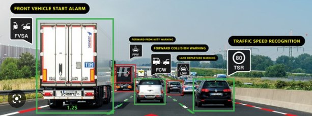
Cameras, Radars, Lidars, Ultrasonic sensors are the various kinds of sensors used to develop vehicles equipped with Advanced Driver Assistance Systems (ADAS) and Autonomous Vehicles (AV).
AVs can depend on more than 20 sensors mounted at various locations. Each sensor provides different types of data, such as, cameras provide images, radars and lidars provide point clouds, etc. The Autonomous Driving (AD) software uses information/data from each of these sensors individually and collectively from multiple sensors (Radar + Camera) to make precise driving decisions.
Sensors are the ‘eyes’ of an autonomous vehicle (AV) and they help the vehicle perceive its surroundings, i.e., people, objects, traffic, road trajectory, weather, lighting etc.
This perception is critical, as it enables AV to make the right decisions, i.e., stop, accelerate, turn, reverse, etc.
AVs with higher levels of autonomy (L2+ and above) where autonomous features replace driver tasks, multiple sensors are required to understand the environment correctly.
But every sensor is different and has its own limitations for e.g., camera will work very well for lane detection or object classification whereas a radar may provide good data for long range detection or in different light conditions.
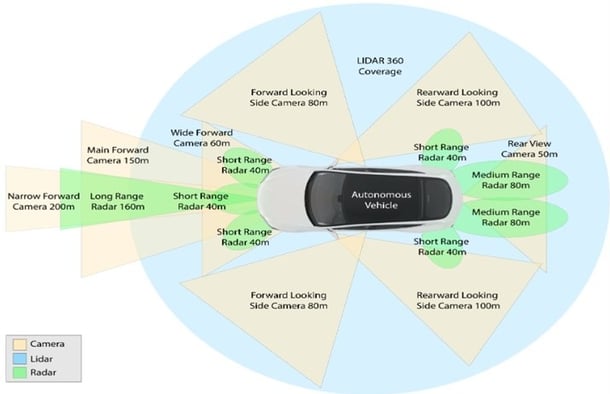
Fig-1: Different sensors in an Autonomous Vehicle assist in making driving decisions
| Capabilities | Camera | Radar | LiDAR |
| Long-range detection | Average | Good | Average |
| Differing lighting conditions | Average | Good | Good |
| Different weather conditions | Poor | Good | Poor |
| Object classification | Good | Poor | Good |
| Stationary object detection | Good | Poor | Good |
Sensor Fusion improves the overall performance capability of an Autonomous Vehicle and there are multiple fusion techniques to choose from, depending on the Operation Design Domain (ODD) feature.
Thus, the AV data collected from multiple sensors is fused using Sensor Fusion techniques, to provide best possible inputs for AVs to take appropriate decisions (brake, accelerate turn, etc.).
Below are a few examples of different types of fusion techniques and depending on the level of autonomy of the AV, one or multiple sensor fusion techniques will be used. For example: for Level 2 feature development only object data, lane fusion, traffic sign fusion may be used as per feature requirement but for Level 3 and above all the techniques of Fusion may be required.
| Type of fusion | Type of sensor used |
| Object data fusion for improving information about stationary and moving objects surrounding vehicle | Camera, Radar, Lidar |
| Lane fusion for improving lane information | Camera, HD-map |
| Traffic sign fusion for improving information traffic sign direction | Camera, HD-Map, Lidar |
| Free space fusion for improving information for drivable-space | Camera, Radar, Lidar |
| Localization for vehicle position estimation | HD-map, vehicle sensors, Camera / Lidar |
The complexity of the environment, feature specifications define fusion strategy and type of fusion requirement needs.
Executing sensor fusion is a complex activity, and one should account for numerous challenges, such as:
These challenges may become more complex with AVs of higher levels. Multiple sensors may be required to get close to a 360-degree coverage and avoid blind spots.
The placement of sensors is also crucial to reduce blind zones and achieve the best performance without compromising safety. This also results in a tradeoff of cost Vs feature requirement contingency.
Additionally, the level of accuracy of every sensor is different and managing the data accuracy of each sensor is critical for the final output. Thus, understanding the problem statement and the environment to account for these challenges is imperative.
To ensure high levels of accuracy with Sensor Fusion, one must set the right KPIs to measure, along with a robust design.
Below are some of the identified KPIs to improve data accuracy:
a. Single track for each object
b. Higher accuracy through design
Below is an example of a Sensor Fusion flow with blocks, that can be used to ensure highest levels of accuracy for Object Detection. There can be different architectures depending on the type of fusion, i.e., High Level Fusion, raw Sensor Fusion, etc.
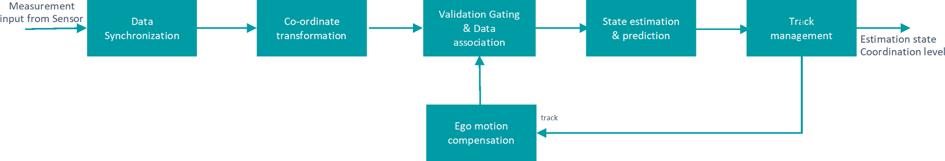
Data Synchronization: Different sensors give different outputs, e.g., camera gives output at 50 milli-seconds and a radar could be giving output at 60 milli-seconds. Data Synchronization technique synchronizes this data before Sensor Fusion is executed
Coordinate Transformation: This is a technique based on geometry and placement of sensors, to bring data from sensors mounted at different locations, into one common frame.
For example, if we consider a car that is 5.5 meters long and 2.5 meters wide vs a truck that is 19 meters long and 5 meters wide, data is required to be brought at rear axle or front axle frame
Validation Gating and Data Association: This is a technique to ensure that multiple data received from each sensor on the vehicle is for the same object, e.g., a truck in front.
Track Management: Track management technique ensures the final output of sensor fusion. It initializes, maintains, and deletes track, based on track history and also calculates track confidence
Ego Motion Estimation: It accounts for the movement of the vehicle. For example, if the data is received in T+100 milliseconds and T+200 milliseconds, but during this time the vehicle has already moved
It is important to use the right validation strategy to test fusion with simulated data, real world data or in vehicle testing, thereby ensuring software quality and scenario covers.
Following are the key aspects for fusion validation:
So, fusion is an extremely critical perception component for AD performance, and one must consider key practical aspects and define the right strategy for design and validation, to achieve highest level of maturity of AD software.
Since the AV depends on such a wide range of sensors, calibration of these sensors becomes very important. Mis-calibrated sensors can have catastrophic impacts in terms of safety and functionality of the AV. Calibration of individual sensors is a long-drawn-out process, and different sensors i.e., LiDAR, radar or cameras etc. require different calibration methodologies. This calibration is typically carried out at the end of the production line.
The general understanding in the industry is that intrinsic calibrations, i.e., geometric distortion, focal length, etc., do not change over time and are typically done only once. However, extrinsic calibration, i.e., position and orientation, which can change based on various reasons, from poor road conditions to sensors mounted on movable car parts such as the side view mirror, is a challenge. For example, a rear-facing camera mounted on the auto-folding side- view mirror, is used for lane change functionality or to detect the presence of a vehicle in the adjacent lane, a yaw angle miscalibration of 0.5 degrees can cause a lateral error of almost one meter depending on the distance to the vehicle. A lateral error of one meter, could result in a vehicle present in the adjacent lane going undetected.
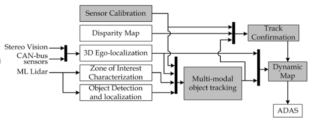
Multi-modal perception block diagram
A multi-modality sensor calibration system requires the following features:
Additionally, it is important to calibrate individual sensors and multiple sensors with respect to each other. Multi-modality sensor calibration refers to the calibration of different types of sensors such as Camera with respect to LiDAR or RADAR about LiDAR.
In an AV, features such as Lane Departure Warning (LDW), Forward Collision Warning (FCW), Traffic Sign Recognition (TSR) rely on the front-facing camera. A well-calibrated camera can position the vehicle in the center of the lane and maintain an appropriate distance from the vehicle in the front.
But a minor error in the pitch angle of the camera mounting can result in the vehicle in front appearing further away than it is. It could result in delayed system response to avoid a collision with a vehicle in the front.
“As a Technology Solutions Provider, Cyient works closely with the industry experts, equipment manufacturers, and aftermarket customers to align with automotive industry trends through our focus areas of megatrends "Intelligent Transport and Connected Products," "Augmentation and Human Well-Being," and "Hyper-Automation and Smart Operations."
All this ensures that the software life cycle will extend beyond five to seven years after SoP (start-of-production)
Harsha has over two decades of experience in Automotive & Hi-Tech Industry with expertise in New Product Engineering & Integration Strategy for ADAS & Self-driving applications, vehicle HMI infotainment connectivity solutions and Device Protocol development. Currently, he serves as ADAS / AD Domain SME under Technology Group.