- 2026-Jun-04
Espen Berg
Our Intelligent Engineering solutions across products, plant and networks, combine our engineering expertise with advanced technologies to enable digital engineering & operations, develop autonomous products & platforms, and build sustainable energy and infrastructure
.png?width=774&height=812&name=Master%20final%201%20(1).png)
Bird's Eye View (BEV) is revolutionizing industries like autonomous driving, surveillance, and augmented reality, by providing a critical, top-down perspective that enhances spatial awareness and precision. As systems become more intelligent and autonomous, the ability to accurately interpret the environment from a BEV perspective is essential for safer navigation, real-time decision-making, and effective monitoring of complex scenarios.
Why is BEV so crucial today? The autonomous vehicles market is projected to reach a staggering $2.16 trillion by 2030, driven by advancements like BEV that enable enhanced navigation and safety. In surveillance, BEV aids in interpreting crowded scenes and tracking movements with heightened accuracy—a key capability within the smart surveillance market, which is expected to grow to $147 billion by 2030. Likewise, in augmented reality, BEV creates immersive experiences and precise spatial interactions, benefiting a sector poised to expand from $37 billion in 2023 to $114.5 billion by 2027.
In this blog, we will dive into the mechanics of BEV, from technical implementation to the critical applications driving its adoption. We’ll also walk through diagrams that clarify each stage, providing a clearer picture of how BEV empowers systems to better interpret and navigate their environments. Join us as we explore why BEV technology is shaping the future across multiple domains and what it means for innovation in today’s tech landscape.
A Bird's Eye View provides a top-down representation of a 3D scene, offering a unique perspective that enhances spatial awareness – a key requirement in areas like autonomous vehicle navigation, robot path planning, and camera-based security systems. This high-level vantage point allows systems to perceive object relationships, track movements, and assess environments more accurately.
In computer vision, BEV is achieved by transforming a camera's default angle (typically front-facing or side-facing view) into a simulated overhead view. This process involves advanced techniques such as homography, projective geometry, and matrix which work together to reorient and warp the image, effectively flattening the scene into a comprehensive, top-down view. The result is a powerful tool for machines to better understand and interact with complex spatial environments, enabling safer and more efficient automated operations.
These diverse applications demonstrate BEV’s transformative impact across industries, making it a key component in advancing automation, security, and interactive technologies.
The primary challenge in generating a Bird's Eye View (BEV) is transforming an image captured from a specific 2D perspective into a top-down view, which involves complex mathematical operations known as projective transformations.
When a camera captures a scene, it creates a projection onto the image plane on its particular viewpoint. To transform this viewpoint into a Bird's Eye perspective, we apply a homography transformation- a process that maps points from one plane to another. Homography leverages the principles of projective geometry, enabling us to “warp” the captured image and recreate the scene as if viewed directly from above. This transformation is essential in BEV applications because it reconstructs spatial relationships in the scene, allowing systems to interpret depth, distance, and relative positioning with high accuracy. Through these transformations, BEV enhances machine perception, making it indispensable in fields like autonomous navigation, robotic path planning, and spatial analytics.
Homography and Matrix Representation
In computer vision, the homography matrix (H) plays a crucial role in projective transformations between two planes. This matrix enables the mapping of points from one plane (such as the camera’s natural perspective) to another plane (like a top-down, Bird's Eye View), providing an essential tool for perspective manipulation.
The homography transformation preserves straight lines, making it particularly valuable for applications like BEV in autonomous driving. By ensuring that roads, lane markings, and objects maintain their correct orientation and positioning from an overhead perspective, the homography matrix helps create a reliable and geometrically accurate view.
Mathematically, the homography matrix is a 3x3 matrix and is denoted as:
$$ H = \begin{bmatrix} h_{11} & h_{12} & h_{13} \\ h_{21} & h_{22} & h_{23} \\ h_{31} & h_{32} & h_{33} \end{bmatrix} $$
This matrix defines the relationship between points in the source image (from the original camera view) and their corresponding points in the target image (the BEV)).
The transformation of a point P(x,y) in the source image to P′(x′,y′) in the target image is governed by the following equation:
$$ \begin{bmatrix} x' \\ y' \\ 1 \end{bmatrix} = H \cdot \begin{bmatrix} x \\ y \\ 1 \end{bmatrix} $$
This equation maps the coordinates from the source image to the Bird's Eye View.
Camera calibration is the process of estimating a camera’s intrinsic and extrinsic parameters to establish the relationship between 3D world coordinates and the 2D image coordinates captured by the camera.
When an image is captured, the camera projects the 3D scene onto a 2D plane, which can introduce distortions. To map points in the 2D image back to their accurate positions in the 3D world (or vice versa), it’s essential to understand how the camera projects and potentially distorts the image. Camera calibration allows us to correct for lens distortion and enables precise mapping of 3D points to their 2D projections, ensuring spatial accuracy and fidelity.
Intrinsic Parameters:
Intrinsic parameters describe the internal characteristics of a camera, defining the relationship between the camera's image plane and pixel coordinates. These parameters include:
These intrinsic parameters can be represented in a matrix, often referred to as the intrinsic matrix K:
$$ K = \begin{bmatrix} f_x & s & c_x \\ 0 & f_y & c_y \\ 0 & 0 & 1 \end{bmatrix} $$
Where:
Extrinsic Parameters:
Extrinsic parameters describe the camera's position and orientation relative to the world. They consist of:
$$ R = \begin{bmatrix} r_{11} & r_{12} & r_{13} \\ r_{21} & r_{22} & r_{23} \\ r_{31} & r_{32} & r_{33} \end{bmatrix} $$
$$ T = \begin{bmatrix} t_x \\ t_y \\ t_z \end{bmatrix} $$
The extrinsic parameters essentially map the 3D world coordinates to the camera’s coordinate system.
Begin by calibrating the camera to obtain its intrinsic and extrinsic parameters. Typically, this is achieved using a chessboard calibration technique. The known geometry of the chessboard provides a reliable reference, allowing the system to compute the necessary camera parameters accurately.
Next, identify key points (such as corners, edges, or road markings) in both the original camera view and the desired top-down BEV plane. Establishing correspondences between these points is crucial to compute the homography matrix that will transform the perspective.
With the homography matrix calculated, you can warp the original image into the Bird's Eye View by applying the matrix transformation to each pixel. Many computer vision libraries, such as OpenCV, provide functions to streamline warping operation. For instance, the 'warpPerspective' function in OpenCV enables this transformation:
Warp the image to Bird's Eye View using the homography matrix
bird_eye_view = cv2.warpPerspective(image, homography_matrix, output_size)
After warping the image, some post-processing may be necessary to address any distortions or artifacts caused by the transformation. Techniques such as edge detection, filtering, and contrast adjustment can enhance the clarity and quality of the final the final Bird's Eye View.
In complex systems, especially those in autonomous vehicles, multiple cameras are used to generate a 360-degree Bird's Eye View. These cameras capture overlapping fields of view requiring sophisticated stitching algorithms to seamlessly combine them into a single, coherent top-down image. This multi-camera approach expands the BEV's field of view, improving environmental awareness and navigation precision.
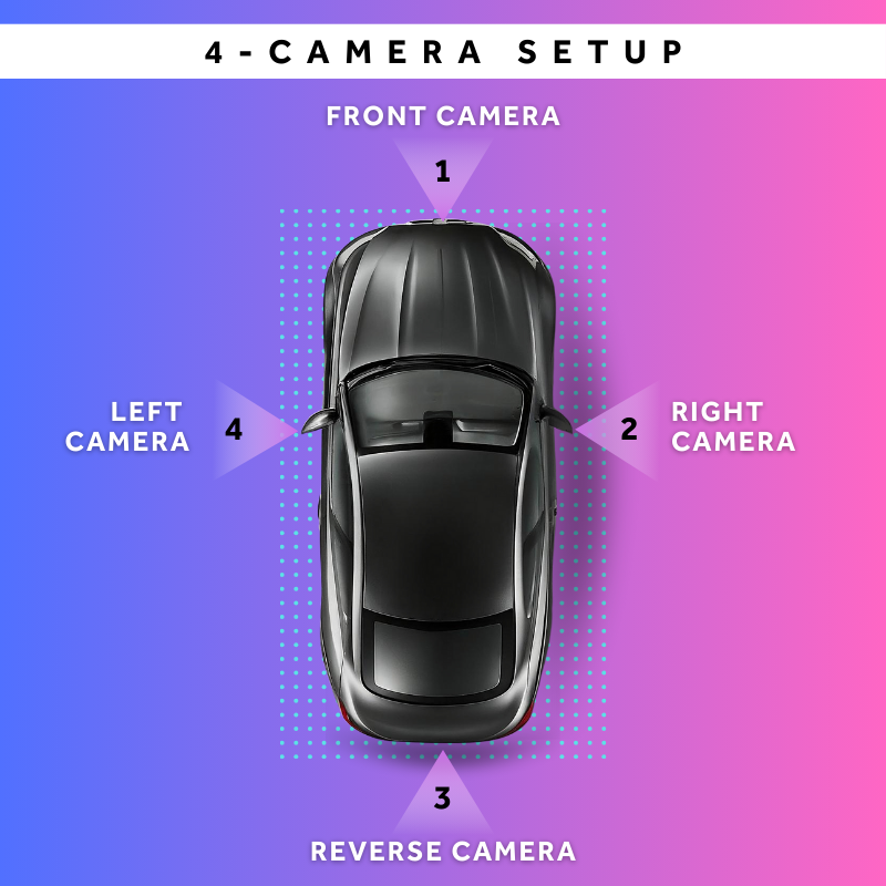
Multi-Camera Setup for 360° BEV
Once generated, the Bird’s Eye View can serve as input for object detection algorithms allowing for the identification of vehicles, pedestrians, and obstacles from the top-down perspective. This approach enhances safety and reliability in applications like autonomous driving by providing a comprehensive view of the surrounding environment, making it easier to track and respond to potential hazards.
Bird's Eye View (BEV) is a transformative computer vision tool that converts scenes into top-down perspectives, enhancing spatial understanding and decision-making in applications such as autonomous driving, surveillance, and robotics. Implementing BEV involves critical steps, including camera calibration, homography computation, and image warping, to generate precise overhead views.
Advancements in multi-camera configurations and deep learning are continuously refining BEV technology, expanding its capabilities in spatial perception and real-time decision-making. Mastering BEV implementation empowers developers and engineers to build more intelligent, reliable vision-based systems across diverse fields.
At Cyient, we have developed a BEV framework tested with four top-mounted vehicle cameras. Our solution manages camera calibration, projection matrix generation, image projection for BEV, and image stitching to produce a seamless 360° surround view. To ensure accuracy, we have established a dedicated vehicle physical simulation lab for BEV framework testing and a camera calibration facility to fine-tune camera parameters.
About the Author

Purushothama is a software architect/developer and has pursued his master’s in VLSI Design. He has over 15 years of embedded and automotive industry experience with an interest in building new end-to-end AI solutions that accelerate human well-being and developing different autonomous models for human-friendly interactive machines in the automotive and agriculture fields.